
schematic where physical miniature components float in precise geometric arrangement above an architectural blueprint surface.
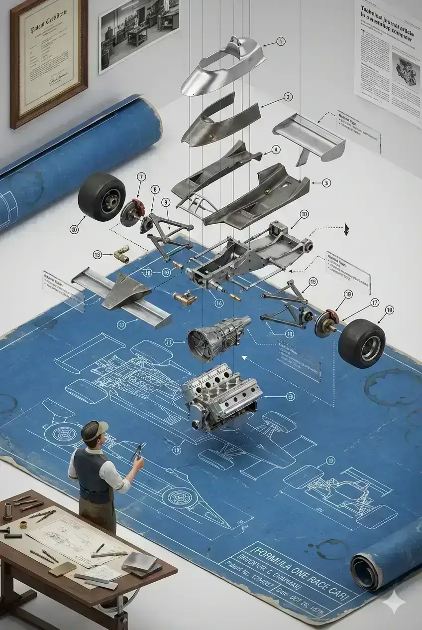
Do this for F1 car: A technical illustration brought to life: an exploded-view schematic where physical miniature components float in precise geometric arrangement above an architectural blueprint surface. Base:: Large format engineering drawing (36" x 24" implied) Aged blue or sepia blueprint paper with white/cream lines Complete orthographic projections: top, side, front views Dimension lines, measurements, tolerances marked Title block with: [INVENTION NAME], [INVENTOR], Patent No., Date Scale notation and drawing standards Coffee cup rings and rolled edges showing use Exploded components (hovering in space): 15-30 individual parts suspended by invisible wire Organized vertically by assembly order (bottom to top) Each component precisely positioned along central axis Spacing proportional to assembly sequence Parts numbered with leader lines to blueprint key Component details: Machined metal parts showing tool marks Fasteners: bolts, nuts, washers, rivets at correct positions Gaskets and seals in appropriate materials Springs, bearings, bushings with realistic finish Largest components at bottom, smallest at top Material finishes: polished steel, cast iron, brass, aluminum INVENTOR FIGURINE PLACEMENT: 1:12 scale figure standing beside blueprint at drafting table Holding dividers or technical pen Looking up at floating assembly Period-appropriate engineer's attire (vest, rolled sleeves, visor) Additional tools on table: T-square, compass, protractor ANNOTATION SYSTEM: Numbered callouts (001-030+) matching blueprint key Dotted leader lines connecting parts to blueprint Transparent acrylic tags floating near components Material specifications etched on tags Assembly direction arrows showing insertion paths SUPPORT ELEMENTS: Miniature machinist tools: calipers, micrometers, gauges Material samples: metal stock, fastener boxes Manufacturing process cards Quality control inspection stamps Engineering change orders showing revisions CROSS-SECTION DETAIL INSETS: Small magnified views showing critical interfaces Thread details on fasteners Bearing race tolerances Surface finish requirements Welded or brazed joint details HISTORICAL CONTEXT: Patent certificate in ornate frame (background) Workshop photograph showing actual manufacturing Company letterhead and correspondence Technical journal article featuring invention Awards or recognition certificates LIGHTING STRATEGY: Bright even illumination on blueprint (lightbox effect) Directional spotlights on each floating component Subtle shadows cast onto blueprint surface Rim lighting on metal edges creating separation No harsh shadows - technical illustration quality MATERIAL REPRESENTATION: Visible grain in cast components Polished surfaces reflecting light Oxidized or weathered finishes where appropriate Material texture variation: rough castings vs. machined surfaces Authentic period manufacturing techniques evident SPATIAL ORGANIZATION: Perfect axial alignment of all components Consistent spacing between adjacent parts Rotational orientation showing key features Subassemblies grouped with slight clustering Total assembly height 24-30" above blueprint PERSPECTIVE: Isometric or slightly angled axonometric view maintaining technical accuracy COMPOSITION: Central vertical axis with components stacked, inventor at lower left corner ASPECT RATIO: 3:4 (vertical) to accommodate component stack STYLE: Technical illustration photography, Haynes Manual aesthetic, Engineering Graphics Standards
Prompt Information
Category
illustration
Created
6 months ago
Views
300
ID
#654
Related on PromptHub
technical infographic of [HARD DISk] with a 45-degree isometric 3D perspective showing the device slightly tilted to reveal depth and dimension
technical infographic of [HARD DISk] with a 45-degree isometric 3D perspective showing the device slightly tilted to rev...
schematic where physical miniature components float in precise geometric arrangement above an architectural blueprint surface.
schematic where physical miniature components float in precise geometric arrangement above an architectural blueprint s...
Oppenheimer — minimalist movie poster, constructed from symbols/particles) A minimalist movie poster for Oppenheimer.
Oppenheimer — minimalist movie poster, constructed from symbols/particles) A minimalist movie poster for Oppenheimer.
infographic image of [Eye], combining a realistic photograph or photoreal render of the object with technical
infographic image of [Eye], combining a realistic photograph or photoreal render of the object with technical
infographic of the US Dollar banknote, treated as an engineered object.
infographic of the US Dollar banknote, treated as an engineered object.
infographic image of Kaaba, combining a realistic photograph
infographic image of Kaaba, combining a realistic photograph
Explore on the BrightCoding network
Hand-picked resources from our other sites.
Stop Memorizing C Syntax! Build These Insane Systems Instead
Discover SWPFlow's C-Project-Based-Tutorials: 40+ hands-on projects to master systems programming by building databases, kernels, compilers, and game engines fr...
Stop Paying for System Design Courses! Use This Free Repo Instead
Discover the free GitHub repository awesome-system-design-resources that helps developers master system design interviews without expensive courses. Learn about...
Stop Scraping Finance Data Manually! FinNLP Does It All
FinNLP by AI4Finance Foundation automates LLM training pipelines for financial data. Learn how to collect news, social media, and SEC filings across US and Chin...